
 Manual
 Firmware
 Software
 Useful terms
 FAQ
FAQ Guarantee terms and conditions
3DGENCE SLICER
-
Nylon
A group of polyamide materials developed by DuPont company. Currently, these are used also for producing resistant filaments for 3D prints. Its main advantage includes its high mechanical and chemical strength, possibility of further processing and coloring with textile dyes. Prints feature also some flexibility and resistance to rupture.
-
Nozzle
A head component coming into direct contact with the print. The nozzle heated to temperature specific for a material makes it flow and forms a thread of plastic with a rated nozzle diameter. The 3DGence ONE printer as standard is equipped with a 0.4 mm nozzle. The nozzle outlet diameter affects the available resolutions, print speed and accuracy.
-
Knurl
This is an extruder part, driven by a stepper motor. It makes it possible to accurately feed the plastic wire to the printer nozzle thanks to its concave, “toothed/knurled” recess that “bites” into the plastic wire. An element that strictly cooperates with the knurl is the clamp providing a correct contact between the knurl and the filament.
-
HIPS
High-Impact Polystyrene – a styrene polymer. It is used mainly in 3D printing as a material for printing support structures for ABS plastic. It is soluble in d-limonene. It features a high impact resistance and a low flexibility.
-
G-code
This is a normalized programming language adjusted to control CAM machines. In simple words, the G-code string includes machine instructions – in what direction, how fast and along which axis to move. The code for printers is generated by slicing software (slicers). It stores all the data on subassembly temperatures and the revs of motors in a precision sequence that results in moving the hotend and defines the extruder behavior. The code commands are sent line by line to the printer controller processor during the printing process. The processor interprets the code based on its software and sends specific signals to particular components.
-
Firmware
It is responsible for the interpretation of the commands contained in the machine code (G – code). The effect of its work are the basic signals for heaters, motors and fans. It is responsible for the interpretation of accelerations, temperature correction tables and many other factors. Well-tuned firmware is an important element of machine calibration, because it is responsible for the regulation of breaks, accelerations and other key parameters for good performance of the device.
-
Filament
Popular description for material used to print in fused deposition modeling (FFF) technology. The filament is a thermoplastic wire (PLA, ABS, PVA, HIPS, PC, Nylon or other) generated with specific tolerances The filament is wound on a spool. The relevant parameters when selecting a filament include: dimensional tolerance and the method for protection against moisture (optimally the filament should be vacuum packed with a moisture absorber.) A high diameter of the spool hub provides an opportunity to use its entire length – an excessive bending of the filament (e.g. on a small spool hub) can cause problems with its application. The filament after opening the package should be stored in a dark, dry place with a moisture absorber.
-
Extruder
A part of the 3D printer working in the FFF technology. It is designed to feed the filament at a strictly defined rate, and consequently – quantity. The 3DGence ONE printer is fitted with a Direct Drive type extruder. It means that extruder motors are located beyond the moving printer parts, leading material to the head via the PTFE tubing. It makes the design lighter and has a positive impact on the print quality.
-
Endstop
An optoelectronic switch that limits a 3D printer movement beyond the maximum range. The device is fitted with 3 optical endstops – one for each axis. The optical endstop does not require any physical contact with the corresponding interrupter, which provides its long life, however one should notice that it is sensitive to the sources of bright light which may result in triggering its false operation.
-
Brim
One of the methods of improving print adhesion to the bed. It consists in increasing the adhesion surface to the bed by generating additional, external brims of the solid at the level of the first layer of the print. The more brim lines will be added, the larger will be the adhesion surface. Typically, from 5 to 20 brim lines are used. The brim should be used, in case of problems with detaching prints from the bed.
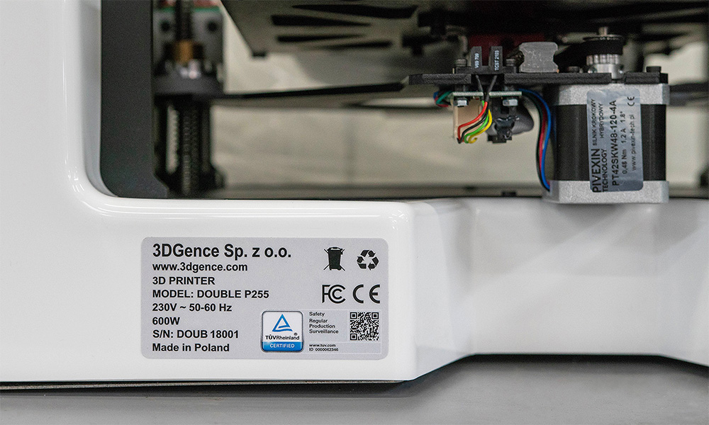
Where is the serial number of the printer?
The printer’s serial number is on the sticker located on the back of the printer.
The serial number begins with the symbol: S/N DOUB.
How to turn on the printer for the first time?
efore first use the printer, read the quick start guide attached to the device. The quick start guide is also available here in the attachment.
1. Open the box and remove the protective styrofoam with accessories box.
2. Take the printer out of the box using the holders. Take off the plastic bag. Please retain all packaging for warranty purposes.
3. Remove the filaments from under the heatbed and unscrew wing knobs on the sides.
4. Remove the yellow shipping clips and the heatbed securing tapes. Make sure that nothing is left on the heatbed.
5. Screw the spool holders to the printer sides.
6. Attach the bowden tubes from filament sensors to the extruders.
To do this, on the filament sensors and on the extruders:
a) take out the collet clip (red colour in the „quick start guide”),
b) push in the ring (yellow colour in the „quick start guide”),
c) insert bowden tube (blue colour in the „quick start guide”) in to the hole and place the collet clips (red colour in the „quick start guide”).
7. Plug the power cable to the printer and set the power switch to the “on” position.
8. Follow the instructions on the display.
9. Unpack the filaments and place them on the spool holder. Model material (PLA) on the left spool holder. Support material (BVOH) on the right spool holder. Load filaments by choosing from printer’s menu: Materials → Load model material/Load support material and follow steps.
10. Place SD cart in the slot. Print the prepared model from SD card by choosing the file from Print menu.
WARNING! Insert SD card into SD card slot with SD card’s pins upwards.
How to load the filament?
- Check that the filament spool holder and guide system are correctly installed on the printer. The assembly of these elements is described in the “Quickstart” card attached to the printer.
- Make sure that there is no material installed on the filament spool holder you want to install the new material on. This also applies to the presence of filament in the guide system and in the extruder (not applicable to the first material installation). If the material is loaded, first use the option Unload model material/Unload support material available in the printer menu.
- If there are no pieces of material on the holder or in the gudie system, you can continue loading the material. From the MATERIALS menu, select the LOAD MODEL MATERIAL option located under the TOOL 0 extruder or LOAD SUPPORT MATERIAL located under the TOOL 1 extruder. A filament loading assistant will be started, subsequent commands will be displayed and the user will be guided through the rest of the process.
- The first step of the assistant’s work is to choose the right temperature for loading the material. To make simpler, the suggested temperature for plasticizing particular thermoplastic materials is given on the screen. It is also possible to set the temperature manually using the – / + buttons in the lower right corner of the screen. After selecting the desired charging temperature, confirm with the CONTINUE button.
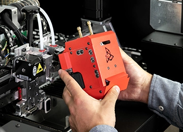
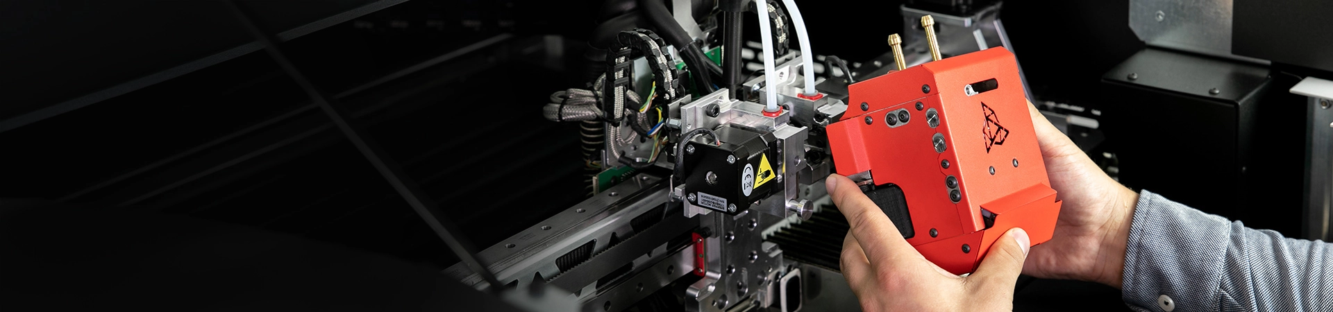
- Cut the filament tip at an angle of 45°, and then place the filament spool on the holder (fig. 1, point 1).
- Insert the end of the filament into the filament sensor input (fig. 1, point 2).
- After activating the sensor, the extruder motor will start. Push the filament so that its tip passes through the entire length of the guide system (fig. 1, point 3) up to the extruder (fig. 1, point 4). If the material has been inserted correctly, it will be intercepted by the extruder, which will be felt as a material draw and resistance when attempting to withdraw it.
- Once the nominal extrusion temperature of the material has been reached, the process will start automatically. The extruder will push the material through the short guide system (fig. 1, point 5) to the material heated up to the plasticizing temperature of the hotend.
- Observe the tip of the nozzle carefully. The device will control a short section of the filament.
- Confirm successful material loading with the CONTINUE button and remove the rest of the pressed material from the working table using tweezers.
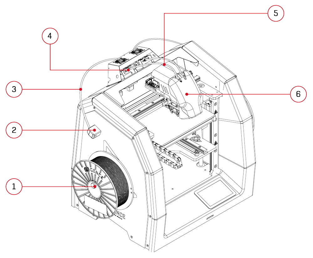
Fig. 1 Identification of the most important elements of the extrusion system:
1. Spool holder | 2. Filament sensor | 3. Long guide system
4. Extruder | 5. Short guide system | 6. Dual hotend module
How to unload the filament?
- From the MATERIALS menu, select the UNLOAD MODEL MATERIAL option located under the TOOL 0 extruder or UNLOAD SUPPORT MATERIAL located under the TOOL 1 extruder. The filament unload assistant will be started. The assistant, displaying next commands, will guide you through the rest of the process.
- Cut the material about 5 cm in front of the filament sensor input opening and remove the spool from the holder. Remember to keep the filament in a dry, unpainted place.
- After reaching the right temperature, the material unloading process will start automatically. Initially, the material will be extruded – it will facilitate the retraction of material in the next step.
- Remove the rest of the filament from the guide system and confirm the end of the assistant’s operation. Until the material is completely removed from the guide system, the extruder motor will rotate, making it easier to pull out, for example, residual material stretched out.
How to change the filament during printing process?
The printer makes it possible to change the material during printing. This option is designed for changing the material when it is finished or when you want to change the colour of the printed model from a certain height. This option is not recommended for multiple-material printouts (e.g. when the bottom of the model is made of ABS and the top of PLA). After unloading the previous material, the printer will store the loading temperature for the new material.
- Press the MATERIALS key on the touch screen.
- Choose the CHANGE MODEL MATERIAL option for Tool 0 hotend or CHANGE SUPPORT MATERIAL option for Tool 1 hotend.
- Confirm the start of the material change manager operation by clicking on CONTINUE.
- The printer will start heating the hotend to the nominal extrusion temperature. A test section of the filament will be extruded and then, the material will be withdrawn from the extruder.
- Slide the end of the material out of the bowden tube manually and remove the spool from the holder.
- Cut the new filament end at the angle of 45o and place the spool with material on the holder.
- Slide the filament end into the input opening of the filament sensor.
- The extruder motor will start after activation of the filament sensor. Push the filament so that its tip passes through the entire length of the bowden tube up to the extruder.
- When the nominal material extrusion temperature is reached, the process will start automatically.
- Observe the nozzle tip carefully. The printer will perform a test-extrusion of a short section of the filament.
- Confirm successful loading of material with “CONTINUE” key and remove the remaining extruded material from the heatbed.
- The printer will restart the printing process automatically.
How to solve problems with loading/unloading filaments?
Case 1: The material does not exist in the printer’s memory (MATERIALS), although it is actually loaded to the printer.
Such a case may be caused by choosing the Factory Reset option without first unloading the material. Then only the LOAD MODEL MATERIAL/LOAD SUPPORT MATERIAL option is available, even though the material is already installed. When you try to load the material automatically, the printer will display a message informing that the material must be unloaded manually.
In such a case, unload the filament manually and load it again. In order to unload the material manually:
- Make certain that the heatbed is empty.
- Activate the appropriate hotend from which you want to unload the filament MENU → Activate Tool 0/Acticate Tool1
- Heat the hotend up to the nominal temperature (for example, 210°C for PLA): TUNE → Tool 0/Tool 1 and using +/- key set the temperature.
- Perform a test-extrusion of a filament section using the Extrude option in the MENU.
- Press the Retract key in the MENU in order to guide the filament end to the extruder. Pull the material gently at the input opening and remove the material from the bowden tube.
- After manual unloading, load the material again using the LOAD MODEL MATERIAL/LOAD SUPPORT MATERIAL option.
Case 2: Failure to load material.
The printer will automatically withdraw the material to the bowden tube. Slide the material out of the filament sensor and cut the material end at the angle of 45° and repeat the material loading procedure.
Case 3: Failure to load the material due to blockage of the filament in the short bowden tube, behind the extruder.
If the printer can not withdraw the filament automatically, for example, due to blockage of the filament in the short bowden tube, and the filament has exceeded the encoder threshold, unload the material manually.
Manual unloading of filament:
- If the material is in the hotend, heat the hotend up to the plasticization temperature of the given material and wait for the hotend to reach the preset temperature: TUNE → Tool 0/Tool 1 and using +/- key set the temperature.
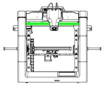
- To loosen the extruder clamp:
a) loosen the knurled nuts (fig. 1, red colour),
b) pull the extruder clamp (fig. 1, green colour). - Pull the material strongly at the filament sensor opening and slide the material out of the bowden tube.
- Cut the filament end at the angle of 45° and repeat the filament loading procedure.
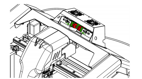
Fig. 1 Loosening the extruder clamp
If the material is blocked so strongly that it is impossible to unload it manually and slide it out of the extruder and the filament sensor, the short bowden tube can be dismounted in order to remove the blockage. There are two bowden tubes for each extruder in the printer. The first, longer bowden tube made of Teflon connects the filament sensor with the extruder, while the second, shorter bowden tube connects the extruder with the hotend.
In order to quickly dismount the short bowden tube:
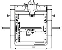
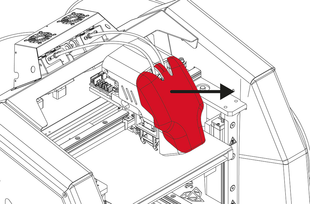
- Remove the front casing of the module (fig. 2) by pulling it towards to you.
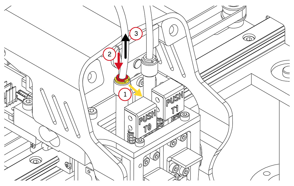
- Slide out the C-shaped pipe connector lock (fig. 3, step 1).
- Press the pipe connector lock (fig. 3, step 2), simultaneously, slide the bowden tube out of the pipe connector opening (fig. 3, step 3).
- Push the filament down and then with a quick movement pull it out of the hotend.
Warning! The hotend must be heated to the plasticizing temperature of the given filament. - Confirm that there are no remains of material on the drive gear. Otherwise, clean the drive gear using a brush or tweezers.
- When inserting the short bowden tube back into the pipe connector opening, remember to slide the bowden tube until resistance is felt (about 2 cm).
- Install the C-shaped lock.

Fig. 2 Removing the module casing
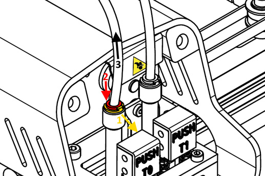
Fig. 3 Sliding the bowden tube out
WARNING! Remember to tighten the knurled nuts after the all operations.
What does Material T0/T1 feed malfunction detected on the display mean?
This information means that the extrusion quality indicator value has exceeded the threshold value. In other words: the flow of the filament decreased below the set value (Flow rate monitor). The tangled filament, an irregular material diameter or the end of filament may be the reasons of occured the message. The appearance of this message does not interrupt the printing proces but pauses it. It allows the user to check what triggered the message, remove the cause and resume printing.
If the problem occurs:
- Unload and load again the material using the Change model material/Change support material option in the printer menu and then resume printing using the Resume option.
- If the Change material procedure is not completed successfully, you should follow the description in FAQ: How to solve problems with loading/unloading filaments?
If the problem persists and points 1 and 2 do not help, check that:
- the printer referencing takes place at a proper height (User’s manual, chapter III, point 3.1),
- material has been loaded correctly and there are no factors that can hinder its movement,
- the material is not damp (otherwise, characteristic air bubbles occur on the filament during extrusion),
- the bowden tube is not mechanically damaged.
If this error occurs repeatedly, replace the hotend with a new one and contact the 3DGence technical assistance department (overlap: REPORT PROBLEM).
How to remove the model from the heatbed after printing?
When the printing process is completed, the cooling sequence will start automatically. The display will show the progress pie chart of the cooling process. When the printer reaches a safe temperature, the display will return to the main MENU.
ATTENTION: after finished printing, the Skip Cooling option is available in the printer’s menu. This option makes it possible to skip the cooling process. However, it may be used only by the users who have considerable experience in the printer operation. Make sure that the hotend is cooled and positioned at the X-axis zero position (maximally on the right) to prevent burn injuries.
Remove the printout from the heatbed using a spatula delivered together with the printer. To do this, gently lever the printout on its sides. Do not use sharp corners of the spatula but only its flat edge. Do not remove the printout by force as it may cause damage to the heatbed. In case of problems when separating the printout from the heatbed, it is recommended that the heatbed should be heated and cooled down again. This process may be repeated and it is recommended for printouts with a large base surface. Always use the spatula to lever the printout.
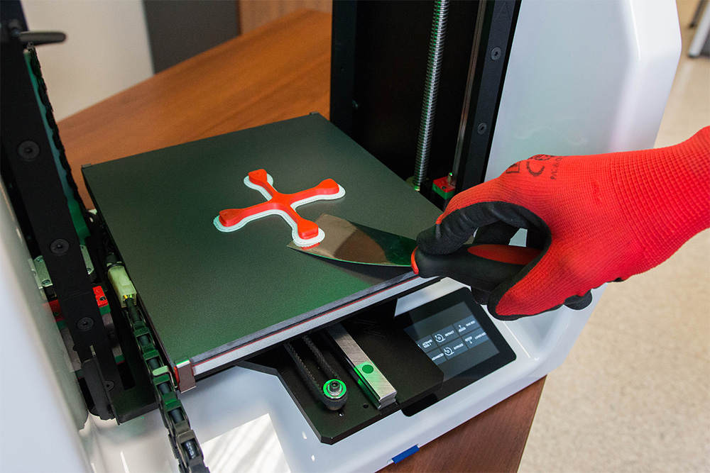
ATTENTION: Do not touch the heatbed surface with bare hands. Otherwise, the heatbed surface will be soiled and there will be problems with adhesion of next printouts to the heatbed surface. Use clean protective gloves.
What software is intended for 3DGence DOUBLE P255?
The dedicated 3DGence Slicer software containing the ready-made print settings for dedicated materials has been prepared for 3DGence printers. The software is used for preparing machine codes – .gcode – from files describing spatial geometry in STL format. The manufacturer ensures full support concerning the use of the prepared printing profiles in the software and recommended printing materials.
The option for changing the print settings is available for advanced users. Due to the character of parameter modifications, the manufacturer does not guarantee the quality and repeatability of printouts prepared in this way.
Download the software with the user manual from the website:
https://3dgence.com/support/
At the first start of the program, the user will be asked for permission to automatically update the printing profiles. We recommend that this option should be enabled to get the best possible model quality. This option can be enabled or disabled at any time. Updates take place every time the program is started.
What do the temperatures on the printer display mean?
At the bottom of the main menu, there are fields containing information on temperatures and status of the printout cooling fans.
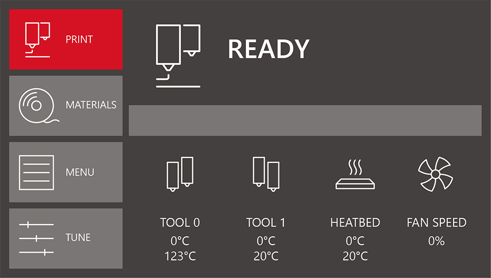
Tool 0 – temperatures for extruder 0 hotend:
• preset temperature (at the top),
• current temperature (at the bottom).
Tool 1 – temperatures for extruder 1 hotend:
• preset temperature (at the top),
• current temperature (at the bottom).
Heatbed – temperature of the printer’s heatbed:
• preset temperature (at the top),
• current temperature (at the bottom).
Fan Speed – percentage of current power of printout cooling fans:
• preset power (at the top),
• current power (at the bottom).
What does the lighting of the heatbed mean?
3DGence DOUBLE P255 printer is equipped with LED backlight located under the printer’s upper plate. The LED backlight illuminates the printout during the printer operation and is also a form of signalling device.
ATTENTION: The backlight colour indicates the heatbed temperature not the hotend temperature! The hotend temperature is shown only on the display.
GREEN COLOUR – safe temperature of the heatbed (below 40°C). After completed printing, the printout can be safely unloaded.
RED COLOUR – heatbed temperature exceeds 40°C. Do not touch the heatbed – there is a risk of burns. After completed printing, do not remove the printout from the heatbed until the backlight turns green.
WHITE COLOUR – the printer is working. The heatbed is hot – do not touch it. There is a serious risk of burns
YELLOW COLOUR – failure of the heating devices. If the hotend has been installed correctly, immediately disconnect the printer from power supply and contact the 3DGence technical assistance department (overlap: REPORT PROBLEM).
What to do if any problem with the printer occurs?
- Report a problem with the device using the form available on the website www.3dgence.com/support in Report problem category.
- Wait for the initial diagnosis and response from 3DGence support.
- When 3DGence support has confirmed that the device has to be sent to the service, send the device within 10 working days to the following address:
- The necessary conditions for accepting the printer on the service repair are:
– registering the device at www.3dgence.com/support and adding a proof of purchase during registration,
– decision of the 3DGence support department about the necessity of sending the device on the service repair,
– filling out the service request form received by e-mail and attachnig it to the package,
– sending to the address: support@3dgence.com information about sending the device on the service repair at least one day in advance. - Sending a printer to the service is synonymous with reading and accepting the regulations included in the service request.
How to replace the hotends?
1. In the ADVANCED menu, choose the HOTEND CHANGE option and choose the hotend you want to change. You can choose T0 hotend (Model Material), T1 hotend (Support Material) or both hotends (Both Tools):
a) if the given hotend still contains filament, the filament unloading manager will be first started,
b) prepare a new hotend and enter the value of the Delta T temperature correction factor which is engraved on the hotend (if there is no engraved factor, enter the default value = 1)
c) wait until the hotend temperature drops below 50oC,
d) switch the printer off and disconnect the power lead.
2. Put protective gloves on.
3. Remove the front casing of the module by pulling it towards you.
- Disconnect the bowden tube from the hotend:
a) slide the C-shaped lock out (step 1),
b) press the connector lock (step 2) and simultaneously slide out the bowden tube (step 3).
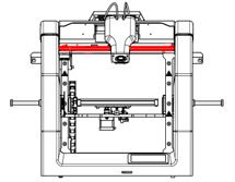
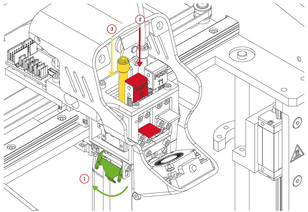
5. With one hand, gently bend the stopper to the left (in the case of T0 hotend) or to the right (in the case of T1 hotend) – in figure below, marked in green. At the same time, press fully and hold the PUSH key (red colour) and push the hotend up while holding it from the bottom with your hand (yellow colour). Make sure that the hotend does not fall on the ceramic heatbed under its own weight.
6. Take the previously prepared new hotend:
Gently bend the stopper and simultaneously press fully and hold the PUSH key. Insert the hotend into the clamping ring until resistance is felt and release the PUSH key and the stopper. When inserting the hotend, make sure it is set correctly – the contacts should be directed outwards and the horizontal groove should be directed towards the user. Next, slide the bowden tube into the hotend. Properly installed short bowden tube will be visible in the hole in the hotend guiding sleeve.
ATTENTION: Be especially careful when inserting the hotend. To avoid bending the contacts, the hotend must be kept in vertical position. If the contacts are damaged or the hotend is incorrectly installed, the “DEF” error (no signal from the temperature sensors) will be displayed in the temperature indication field after switching the printer on.
ATTENTION: after each hotend change, perform the calibration of offsets along X,Y and Z axes again (chapter VIII, point 2.2). First perform the calibration of offset along Z axis and then along X and Y axes.
When to calibrate the heatbed?
The calibration process is not required every time the printer is started – it is enough to carry it out every few dozen to several hundred hours of printing.
Calibrate the heatbed if any of the below symptoms occur:
- the printer is to be started for the first time,
- one or more corners or edges of the printout get unstuck or do not adhere to the heatbed,
- one or more corners or edges of the printout are pressed into the heatbed surface (the impression of transparency of a too thinly applied layer, eventually, skipping, clicking of the extruder motor, accumulation of excess material between the hotend passages),
- the heatbed surface was unintentionally lifted,
- large force has been applied, for example, when removing the printout, and there is a reasonable suspicion that the heatbed has been relocated,
- the first layer seems to be unevenly distributed – one edge is correct while the opposite one is crushed or does not adhere to the heatbed strongly enough.
How to clean the hotends?
Each time after completed printing, clean the hotends by removing the remaining molten/burnt material that may be on the outside of the nozzle.
To do this:
- In the TUNE menu, set the heating temperature for the given hotend using +/- keys. Choose Tool 0 temp. option for T0 hotend and Tool 1 temp. option for T1 hotend.
- Ensure good access to the hotend using the RISE HEATBED or LOWER HEATBED option in the MENU. Press and hold the keys to move the heatbed smoothly up or down. Press the key once to move the heatbed at a short distance.
- Using a non-flammable material or tweezers, gently remove the remaining molten/burnt material.
- After cleaning the hotend, switch the heating off (TUNE → Tool 0 temp. / Tool 1 temp. → RESET).
3DGence DOUBLE P255 printer can also clean the hotends automatically by extruding a section of material. This function is particularly useful when the user has to change the material or remove the remains of old filament or if the hotend has not been used for a long time and is slightly clogged. The automatic hotend cleaning assistant is available during printing and in the idle mode.
Hotend cleaning assistant:
- Choose MATERIALS and then CLEAN NOZZLES in the main menu.
- Specify the hotend to be cleaned – MODEL MATERIAL for T0, SUPPORT MATERIAL for T1 or BOTH TOOLS for both hotends. Confirm the choice with CONTINUE key.
- The process will start automatically.
- After completed process, remove the rest of the filament extruded from the hotend.
How to clean the heatbed?
Dirty or greasy heatbed may seriously hinder or make printing impossible. It is recommended that the heatbed should be cleaned before each new printout.
Clean the printer’s heabed by following the instructions below:
- Set the printer’s heatbed in a position that makes it possible to clean the heatbed easily (MENU → RISE HEATBED / LOWER HEATBED).
- Switch off all heating elements of the printer and wait until they are cooled down completely.
- Switch the printer off using the main switch and disconnect the printer from the power source.
- Put protective gloves on.
- Remove any residual plastic from the heat bed surface using the spatula. Next, soak a cotton (non-synthetic) cloth with a solvent:
• 10% spirit vinegar,
• acetone,
• nitro cleaner,
• extraction naphtha
or clean the heatbed using a sponge soaked in detergent.
When degreasing, pay special attention not to expose the printer components made of plastic and painted components to action of a solvent as it may damage them. - Wait for the solvent to evaporate completely.
ATTENTION: There are OHS instructions on the packaging of the solvents. The instructions must be strictly observed – the solvent vapours may be harmful.
Where is the latest version of the printer firmware?
The latest printer firmware is in the FIRMWARE category: https://3dgence.com/support/
The FIRMWARE category is available after creating an account and registering the device.
How to change the heatbed in the printer?
- Switch the printer on and make certain that the heatbed temperature is lower than 30o
- Lower the heatbed (MENU → LOWER HEATBED) so that you get free access to the heatbed from the top.
ATTENTION: the heatbed downward movement by means of LOWER HEATBED option is unlimited! Take special care when using this option to prevent the collision of the heatbed with the printer’s lower plate. - Switch the printer off and disconnect the power lead.
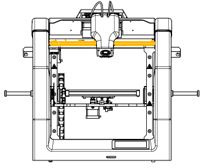
- Remove four metal clips fastening the ceramic surface by sliding them off (fig. 57, yellow colour, point 1). If it is difficult to remove the clips, use pliers.
- Gently raise the ceramic surface upright (fig. 1, red colour, point 2).
- Gently install a new, clean ceramic surface and fix it with clips.
- Clean the ceramic surface (FAQ: “How to clean the heatbed?”).
- Calibrate the heatbed: Menu → Advanced → Heatbed scan.
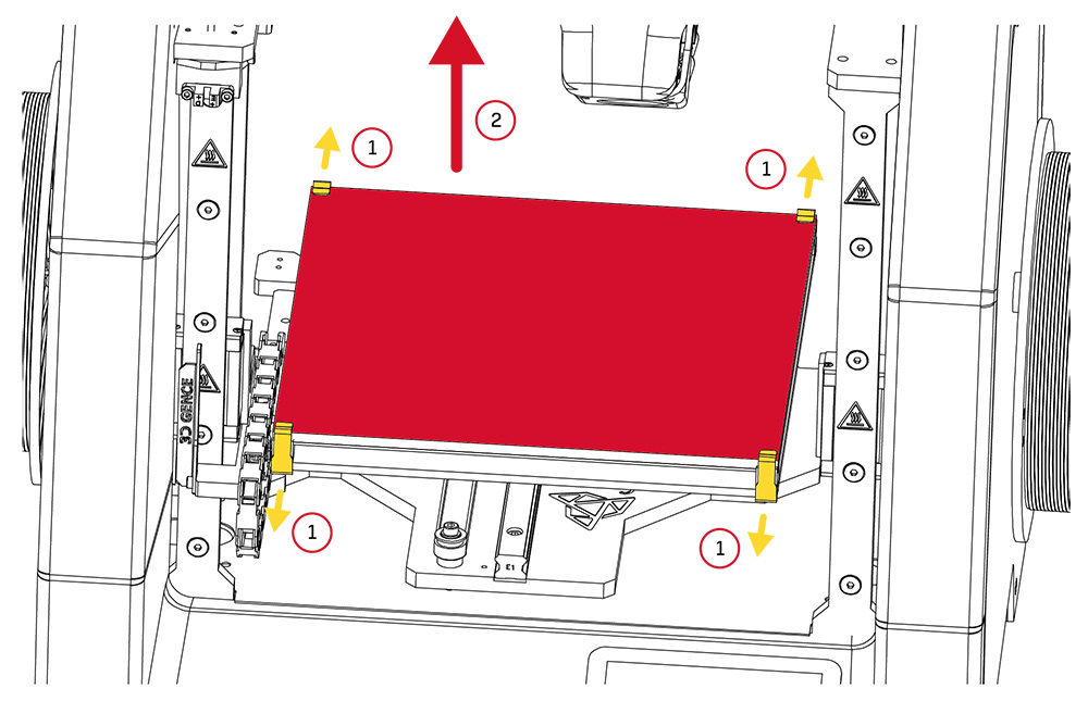
Fig. 1. Heatbed: 1. Clips | 2. Ceramic heatbed surface